

The servos are controlled by a printed arduino uno r3 circuit board. The photo shows a test setup. It is convenient to always have this at hand. Purchase extra boards for mounting under the table. Required for this test setup is an Arduino Uno R3 itself, a protoshield for an additional piece of electronics, a breadboard, jump wires, some electronic components and a servo. In case of a continuous point switch, a relay or switch is required for polarity reversal. On the right side of the Arduino board in the photo, the "prototype shield" is visible. Recently purchased for a few euros, it allows easy addition of electronic components without soldering using the included mini breadboard. Later, the board can be used without the mini breadboard to permanently solder the components, as shown further on this page.

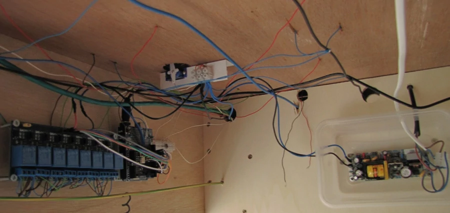
The photo shows how to solder the components if you want to get rid of the test breadboard. An additional three-pin plug-in connector has been added. The two outer pins are the digital rail voltage (DCCIN). The middle pin is the common GND if the servos are connected to a separate power supply. From this board, only the pins on the bottom left of the board remain to send the signal to the servo or polarity relay. When powering the whole system, make sure that it is sufficiently dimensioned. In my case, I have provided each Arduino with a 9-volt power supply and provided the servos and relay board per Arduino with a 5-volt power supply.

